Definitions, Attributes & Modifiers
Introduction
An overall insight on the Tally technology, the development language and the tool has given us a strong foundation over which we can proceed and explore the various domains of Tally Definition Language.
As we know, TDL is a definition language. This provides the users with named definitions which allows them to specify a set of properties/attributes for those definitions.
Every definition should have a name and it should be unique. Definitions are enclosed within square brackets. All the interface elements, data elements, style elements and procedural elements are created using definitions. The order in which the specific attributes/properties come into effect is purely based on user interaction.
This is unlike a procedural language where the complete sequence of execution is in the hands of the programmer.
The properties of definitions are referred as attributes. Attributes decide behavior of the definitions. We have a set of modifiers which allow the programmer to alter either the definitions or the corresponding attributes.
This chapter will help us to cover the concept of definitions, its categorization and then progress with the discussion for attributes, its types and modifiers.
Definitions
A definition is identified by its type and unique name. TDL is a definition language based on object oriented programming concepts which strongly emphasizes on re-usability. Once a definition is created, it can be reused any number of times. Not only the definition can be reused but new features can be added along with existing ones.
A definition is created as:
Syntax
[<Definition Type> : <Definition Name>]
All definitions start with an open square bracket and end with a closed bracket.
Where,
<Definition Type> is name of predefined definition types available in the language. For example, Collection, Menu, Form, Part, Line, Report, Field and so on.
<Definition Name> is any user defined name which the user provides to instantiate the definition i.e., whenever a definition is created a new object of a particular definition type comes into existence.
Example:
[Part: PartOne]
In the example the type of definition is part and the name of definition is PartOne. The combination of definition type and definition name must be unique. There are 20 definition types in TDL. Proper naming conventions allow us to ensure uniqueness and better code readability/clarity across projects.
Naming Conventions for Definitions
- Definition name must be unique for a particular definition type
- Definition names are case and space insensitive
- Special characters are not allowed
- Definition names should not start with numerals
- The reserved words cannot be used as a definition Name
- The definition names that have been used by default TDL cannot be given as a definition name by user. If required, the default definitions can be reused or modified.
It is strongly recommended that definition names be meaningful and indicate the functionality of the element being defined.
For example, prefix MBS to indicate My Balance Sheet for all definition used in a TDL program to create Balance Sheet report.
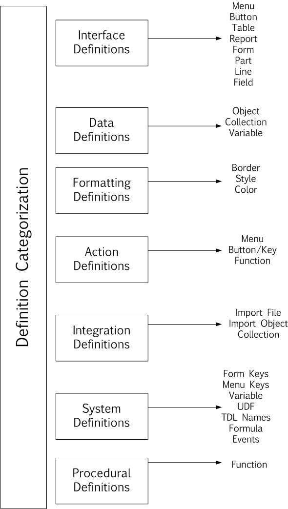
Definition Categorization
There are twenty definitions in TDL which can be categorized based on their functionality and usage. Some definitions are used to design the interfaces and control the presentation layers. Few suffice the fundamental requirements of data gathering and processing requirements. The procedural capabilities included in the language are also provided using definitions.
The broad categorization is given as below:
- Interface Definitions
- Data Definitions
- Formatting Definitions
- Integration Definitions
- Action Definitions
- System Definitions
- Procedural Definitions
Refer to the image for further details:
Interface Definitions
These definitions control the construction of the interfaces. Mostly oriented at the presentation layers of the application. The various visible elements on the Tally screen are Menu, Report, Button and Tables which fall under the category of Interface definitions. The fundamental interface definition is the ‘Report’. In order to create a Report, the other sub elements will be required which have a predefined containership and cannot exist on their own.
Definitions in this category include:
Menu – A menu displays a list of options. Based on the menu item selected by the user, the action to be performed is determined. The first menu which appears on the screen when Tally starts is Gateway of Tally. A Menu can activate another Menu/Report/call a function.
Report – All the screens in Tally, whether an input screen or an output screen, are created using the Report definition. It requires sub elements Form, Part, Line, Field to define its appearance. A report contains one or more forms.
Form – This is the area which is used to display the contents of a report. A form contains one or more parts.
Part – The form area can be further divided into small sections known as parts. Part consists of one or more lines. Part can contain sub parts which in turn contain one or more lines.
Line – A line consists of one or more fields. The line specifies the order in which the fields are displayed on screen.
Field – A field is place where the data is actually displayed or entered. The data can be a constant or variable data. A field can also contain sub fields.
Button – User can perform an action in three ways i.e., by selecting a menu item, by pressing a key and by clicking on a button. Button definition allows the user to display a button on the Button bar and perform an action.
Table-Table is an alias of definition type Collection. It displays a list of values as Tables. Data from any collection can be displayed as a Table
Resource– A new definition type Resource has been introduced in TDL. This will allow accessing and using the resources (images, icons, cursors, etc.) from a local disk, HTTP/FTP or from a DLL/EXE. The image formats supported at present are BMP/JPEG/ICON/CUR.
The resource thus created can be used in a Part definition using the attribute Image. This is applicable both in ‘Print’ and ‘Display’ mode.
However, when the same report is exported in PDF, only BMP and JPEG are supported. Other file formats will be ignored.
Syntax
[Resource: Name]
Source : <Path to Image file>
Resource : <Name Of Resource>[:<DLL/EXE Name with path>]
Resource Type : Bitmap / Icon / Jpeg / Cursor
Part Attribute – Image
With the attribute Image, it is possible for the resource created by using the Definition Resource to be used in the Part.
Syntax
[Part: Part Name]
…
Image: <Resource Name>
Where,
<Resource Name> is the name of the Resource definition.
Example:
[Part: Part ABC]
Image : CmpImage
The definitions Menu and Button fall under the category of Action and Interface definition both as they control the appearance and perform an Action as well
Example
In the example a menu definition is created with the name My Menu. It contains two items Item A and Item B which is constructed using the various interface definitions as per hierarchy shown.
[Menu: My Menu]
Add: Item : Item A: Display:Rep A
Add: Item : Item B: Display:Rep B
[Report : Rep A]
.
.
[Form :Form A]
.
.
[Part:Part A]
.
.
[Line:Line A]
.
.
[Field:Field A]
.
.
Data Definitions
The definitions which suffice the data gathering, processing, storage and manipulation requirements are termed as data definitions.
Definitions in this category include:
Object – As discussed, TDL is an object oriented language. Whenever we create a new interface definition an object is instantiated. Under the data definition category we are referring to objects which contain data and methods to manipulate its own data. The data objects can further be categorized into internal (predefined) and TDL objects (user defined). TDL follows a hierarchical data structure i.e., an object can further contain a single or multiple sub objects. The various interface elements either pull/push data from/into the data objects. A ledger/group is an example of an internal object.
Collection – The fundamental data gathering and processing element of TDL is the collection definition. The bulk of aggregation, chaining and integration capabilities are delivered using collections. A collection is a group of object/collections. The source of objects in the collection can be either an Internal/TDL object. The definition collection falls under the category of data and integration definition as it provides data processing and integration capabilities as well.
Variables – Variables in TDL are light weight/context free structures which can hold values during the execution of a program. The values of these variables are initialized when it is created and can change during the entire execution of program. It is also possible to perform the various manipulation operations like insert/update/delete/sort and find on a variable.
Example:1
In the example a collection definition My Coll is created which has two objects O1 and O2.
The Object O1 is created using the definition object with name O1.
[Collection: My Coll]
Objects : O1, O2
[Object:O1]
Name : “ABC”
Example:2
The collection definition LedColl is created using the internal ledger objects.
[Collection: LedColl]
Type :Ledger
Formatting Definitions
We have earlier covered the construction elements of the interfaces. These definitions control the appearance of the content or elements on the screen. Definitions in this category include:
Style-Style determines the appearance of the text to be displayed by using a particular font scheme. Font name, font style and font size can be hanged/defined using style definition. In default TDL the pre- defined style definitions are Normal Bold, Normal Italic, and Normal Bold Italic. We can create our own style definitions and apply them as required.
Border – This definition is used to create borders of a specific type. Thin Box, Thin Line, Common Border are all examples of predefined borders which can be applied to Part, Line and Field definitions.
Color-Color definition is used to define a color. A name can be given to an RGB value of color. Once a name is assigned to an RGB color value it can be referred in the color attribute of the field.
Example:
In the example a Color definition New Blue and a Style definition New Style is created and applied to the contents of the field My Field.
[Color: New Blue]
RGB : 102,105,235
[Style: New Style]
Font :”Arial”
[Field :My Field]
Set As : “Hello World”
Style : New Style
Color : New Blue
Integration Definitions
The definitions which facilitate the integration of data from external applications to Tally form a part of integration definitions. Import of data using standard API’s ODBC,XML and DLL is provided using the Collection definition. Though XML is the de facto standard for information interchange in recent times, still there may be a few applications which support SDF/Fixed width format for storing the data. We have the definitions ImportFile and Import Object which enable integration with this format.
Definitions in this category include:
Collection – The collection definition which is primarily a data definition falls under this category. It provides the capability to import data from a variety of discrete external data sources. The data objects gathered through the API’s ODBC, XML and DLL can be further persisted into the Tally database. Allows describing the structure of each record in the ASCII file that is being imported. The field names and the width is specified as the attributes of this definition.
Import Object – Import Object specifies the internal object into which the data being imported is stored. It also defines the mapping of the object being imported to the corresponding internal object.
Example:1
In the example a collection is created using the data gathered from an XML located at an HTTP URL.
[Collection: HTTPColl]
Remote URL : “http:\\localhost\MyFile.xml”: ASCII
Example:2
In the example an definition I45Mast is created to define the structure of the external file being imported and the data is imported into the corresponding Ledger object as defined using the Import Object definition I45Ledger.
[Collection: I45Mast]
Type :I45Name :30
Field :I45Parent :30
Object:I45Ledger
[Import Object: I45Ledger]
Type :Ledger
Storage:Name:#I45Name
Storage:Parent:#I45Parent
Action Definitions
The definitions which allow triggering of an action are categorized under Action definitions. These actions may operate upon a particular definition.
Definitions in this category include
Key – This is the fundamental definition which allows us to to associate an action with the key combination. The action is performed when the associated key combination is pressed.
Button – Along with the interface aspects the prime function of the button definition is also to associate an action on pressing the same. We have an option to provide a key combination performing the same function.
Menu – This definition adds menu items to the Menu which is displayed on the screen and in turn is used to trigger actions associated with them.
Function – A function definition can also trigger an Action. It is possible to trigger a sequence of actions from within a function.
Example:1
In the example a key definition My Key is created which is used to trigger an action Display on pressing the key Ctrl+K.
[Key: My Key]
Key :Ctrl+K
Action:Display:Rep A
Example:2
In the example the menu definition My Menu is created which has a menu item Item A to trigger the action Display.
[Menu: My Menu]
Add: Item : Item A: Display: Rep A
System Definitions
System definitions are viewed as being created by the administrator profile. Any items defined under system definitions are available globally across the application. It is not possible to instantiate a new object of type system unlike other definitions given above. System definitions can be defined multiple times in TDL. The items defined are appended to the existing list.
Definitions in this category include:
System: Form Keys – The key names that are defined under Form Keys will be available by default to all the form definitions.
System: Formulae/Formulas – The formulas which are included in the list if System Formulae/Formulas can be shared by all the TDLs. These are referred as global formulae.
System: Menu Keys – The key names included in the list of Menu Keys will be available to all the Menu definitions by default.
System: TDL Names – In this definition, the frequently used business keywords can be stored as system names. System names are keywords which have an identifier associated to it. The value will be saved only once.
System: UDF – The additional storages required as per the business requirements are created using the definition System: UDF.
System: Variable – If variables are to be declared at the system scope the same is done using this definition. The variable thus declared will be available across all reports in Tally.
System: Events – This definition is used to define certain events and associate the corresponding actions based on the occurrence of the same.
Example:1
In the example below a variable My Variable is defined at the system scope.
[System: Variable]
My Variable : “Value“
Example:2
In the example below an action Display is triggered on the occurrence of the system event Load Company.
[System: Events]
CmpLoadEvent3: Load Company :TRUE:Action:Display:”Balance Sheet”
Procedural Definition
Definition in this category include:
Function – It is possible to include the procedural capabilities in the language using the definition Function. Prior to Tally.ERP 9, the tasks to be triggered from the key/button/menu item used to be only those actions which were provided by the language/platform. Using the function definition, you can now define his own set of tasks to be performed and the same can be triggered from a key/button/menu item. Also, it can be used to perform computations and can be called from within an expression. This can be used in an evaluation or for execution.
Example:
A function definition SI Calc used to calculate the simple interest and return the result to the calling program.
[Function: SI Calc]
Parameter: P :Amount
Parameter: R :Number
Parameter: T :Number
Variable : Interest :Amount
Returns :Amount
01:SET:Interest:(##P * ##R * ##T) / 100
02:RETURN:##Interest
Attributes
Each definition has properties referred to as attributes.
- There is a predefined set of attributes provided by the platform for each definition
- The attributes specifies the behavior of a definition. Attributes differ from definition to
- A definition can have multiple attributes associated with
- Each attribute has a ‘Name'(predefined) and an assigned value (provided by the programmer).
- The values to be set for an attribute can either be a constant or the result of an expression
- The expression may be a combination of methods, variables, formula which may be evaluated based on a condition.
Syntax
[<Definition Type>: <Definition Name>]
<Attribute Name> : <Attribute Value>
Where,
<Attribute Name> is name of the attribute specific for the definition type
<Attribute Value> can be a constant or a formula
Example:1
[Part: PartOne]
Line: PartOne
Example:2
[Form: Form One]
Part: Part One
An attribute can have more than one value separated by “:”. When an attribute accepts more than one value, each sub-value is referred as sub-attribute. The number of sub-attributes allows to classify the attribute as either Single, Dual, Triple.
Syntax
<Attribute Name> : <Sub-Attribute> : <Sub-Attribute>
Where,
<Attribute Name> which is a keyword is called as the primary attribute.
<Sub-Attribute> doesn’t have a keyword associated with it. Primary attributes are recognized based on the keyword.
<Sub-attributes> are recognized based on the pre-defined internal order. If the order is changed the specified action will not take place.
<Sub-Attribute> can be optional.
Example:
Explode : <part name> : <condition>
Here Explode is a primary attribute and <part name> and <condition> are sub-attributes. If the order of <part name> and <condition> is changed, the code will not execute the explode action.
In this example sub-attribute <part name> is mandatory while the sub- attribute <condition> is optional. Sub-attribute finally evaluates to a value which is of a particular data type.
List Type Attribute
There are certain set of attributes which accept only single values whereas some attributes can accept multiple values. The values to be specified can be provided either as comma separated or by repeating the same attribute with n values n number of times (where n can be any number).
In the example below the part PartOne contains two lines LineOne and LineTwo. This can be specified by providing the line names as attribute values for the attribute Line.
[Part: PartOne]
Line : LineOne, LineTwo
;; Here LineOne and LineTwo are separated by comma
[Part: PartOne]
Line : LineOne
Line : LineTwo
;; Observe the multiple occurance of the attribute Line with values LineOne and LineTwo respectively
This type is in contrast with the attributes which accept ONLY one value where these values can fall into the category of Single/Dual/Triple. Whenever multiple values are provided to such attributes the recent value overwrites the previous value.
In the example below we have provided two values to the Set As attribute
[Field: FieldOne]
Set As :”Value One”
Set As :”New Value”
;; Here FieldOne displays the ‘New Value’ as Set As accepts only one value the ‘New Value’ overwrites the previous value
;; ‘Value One’.
Attribute Feature – Discreteness
Discreteness is the property of an attribute. This property is applicable to all the categories of list type attributes. Whenever we say that an attribute can assume multiple values i.e., an attribute is list type, the values which it takes have to be discrete and unique.
Discreteness is a behavior where an attribute cannot have same value repeated multiple times.
Example:
[Form: FormName]
Part: part1, part2, part3
i.e., the part attribute takes multiple discrete values. In this example we cannot say Part: part1, part2, part1
In dual list type attribute, discreteness is applicable only up to the first sub-attribute level. Thereafter the second sub-attribute can have repeated values.
Example:
Set : Var1: “Value1”
Set : Var2: “Value1”
Here, the first sub-attribute has to be unique and discrete i.e., Var1 and Var2 whereas the second subattribute i.e., Value1 can be same. Same applies to triple list attribute type as well. Discreteness is applicable only up to first sub-attribute level.
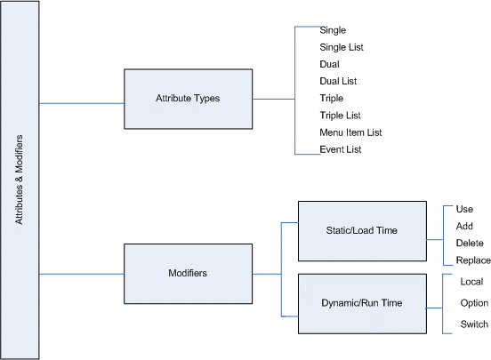
Classification of Attributes
The attributes are classified based on the number of sub-attributes it takes as values (separated by “:”) i.e., either Single/Dual/Triple and the number of items (separated by “,”) to be specified as a value i.e., Single/List.
There are seven types of attributes:
- Single and Single List
- Dual and Dual List
- Triple and Triple List
- Menu Item List
- Event list
Attributes & Modifiers
The Attribute Type Single
In this type the attribute accepts only one sub attribute as a value. This value can be specified only once. The single type attribute can be stated only once per definition. If the attribute having attribute type single is repeated then the definition will take the last value of the attribute, i.e., the previous will be overwritten by the last value.
Example:
[Field: PartOne]
Width : 30
Width : 35
Width : 40
;;Width attribute takes a Single sub-attribute as “40”
The Width attribute is of type Single as it accepts only one sub- attribute as value and this can be specified only once. Other examples of Single attributes are: Set as, Set Always, Scroll, Title etc.
The attribute type Single List
In this type, the attribute accepts only one sub-attribute as a value and the value can be a list i.e., multiple values can be specified for the attribute.
Example:
[Form: Hello]
Part : Hello Asia, Hello World Part : Hello Universe
;;Part attribute takes a single sub-attribute as ‘Hello Asia’. Part is specified multiple times with different values.
The Part attribute is of type single list as it takes one sub-attribute as value and this value can be repeated multiple times
Other examples of single list attributes are Part, Field, and Line etc.
The attribute type Dual
In this type the attribute accepts two sub attribute as a value. This value can be specified only once.
Example:
Repeat : LineOne : CollectionLed
;;Repeat attribute takes the first sub-attribute as “LineOne” and the second sub attribute as CollectionLed
The repeat attribute is of dual type as it takes two sub-attributes as value and the value can be specified only once in a part.
The attribute type Dual List
In this type the attribute accepts two sub-attribute as a value and the value can be a list i.e., multiple values can be specified for the attribute.
Example:
Set : Var 1 : “Tally” Set : Var 2 : “India”
;;The Set attribute takes the first sub-attribute as ‘Var1’ and the second sub-attribute as ‘Tally’. ‘Set’ is specified twice with different set of sub-attributes.
The Set attribute is of type dual list as it takes two sub-attributes as value and this value can be repeated multiple times
The attribute type Triple
In this type the attribute accepts three sub attributes as a value. This value can be specified only once.
Example:
Object : Ledger Entries :First : $LedgerName = “Tally”
/* The object attribute takes first sub-attribute as ‘Ledger Entries’, second sub-attribute as ‘First’ and third subattribute as $LedgerName = “Tally”*/
The Object attribute is of type triple as it takes three sub-attributes as value and this value can be specified only once.
The attribute type Triple List
In this type the attribute accepts three sub-attributes as a value and the value can be a list i.e., multiple values can be specified for the attribute.
Example:
Aggr Compute: TrPurcQty: Sum : $TrPurcQty
Aggr Compute: TrSaleQty: Sum : $TrSaleQty
Aggr Compute: TrQty : Sum : $BilledQty
/* The ‘Aggr Compute’ attribute takes first subattribute as ‘TrPurcQty’, second sub-attribute as ‘Sum’ and third sub-attribute as $TrPurcQty. ‘Aggr Compute’ is specified thrice with different set of sub-attributes. */
The Aggr Compute attribute is of type triple list as it takes three sub-attributes as value and this value can be repeated multiple times
The attribute type Menu Item List
This is a special attribute type which does not fall into any of the categories given above. This is because the number of sub-attributes to be specified is not constant. There are only three attributes in TDL which fall under this category. The attributes are KeyItem, Item and Indent.
Syntax
The syntax of the attribute ‘Key Item’ of Menu definition is as given below:
Key Item : <DisplayName> : <HotKeyCharacter> : <Action> : <Action Parameters>
Where,
<DisplayName> is a string will be displayed for the item added in the Menu.
<HotKeyCharacter> is a character which will activate the required action when it is pressed.
<Action> is an action to be performed ie it can either be a predefined action or an action created using User Defined Function(Call keyword required in this case)
<Action Parameters> The parameter list separated by “:” based on the action specified
Example:
[#Menu: Gateway Of Tally]
Key Item : Sales Analysis
Display : Sales Analysis
Key Item : Purchase Analysis: P : Display : Purchase Analysis
/* The attribute ‘Item’ takes first sub-attribute as ‘Sales Analysis’ second sub-attribute as the hotkey ‘S’ and the third sub-attribute as action ‘Display’ and the subsequent sub-attributes as parameters as required for the action ‘Display”’ The attribute can be specified twice with different set of sub-attributes.*/
The attribute Key Item is of type Menu Item List where the number of sub-attributes for the value vary based on the parameters for the action and this value can be repeated multiple times.
The attribute type Event List
This is a special attribute type which does not fall into any of the categories given above. This is because the number of sub-attributes to be specified is not constant. The attribute ON is enabled for event handling which falls under the category of Event List.
This attribute is provided for the definitions Report, Form, Part, Line and Field.
Syntax
The syntax of the attribute ‘ON’ is as given below :
ON : EventKeyword : <ConditionExpr>: <ActionKeyword>: <Action Parameters>
Where,
<EventKeyword> can be any one of Events provided
<ConditionExpr> should return a logical value
<ActionKeyword> any one of the actions
<Action Parameters> parameters of the actions specified
Example:
[Form: TestForm]
On : FormAccept : Yes :HttpPost : @@SCURL : ASCII : SCPostNewIssue: SCNewIssueResp
/*The attribute ‘On’ takes first sub-attribute as the Event Keyword ‘Form Accept’ second sub-attribute as the condition ‘Yes’ and the third subattribute as action ‘HttpPost’ and the subsequent sub-attributes as parameters as required for the action ‘HttpPost’*/
The attribute On is of type Event List where the number of subattributes for the value vary based on the parameters for the action and this value can be repeated multiple times. The list of actions thus specified will be executed sequentially when the event occurs.
ON is a list type attribute, so list of actions can be executed sequentially when the specific event occurs.
Predefined Attribute Values in TDL
There are certain attributes which take predefined values .The TDL programmer can make use of them. The values accepted must be from the predefined set.
Example:
Scroll : Vertical
Scroll attribute accepts value vertical, horizontal, flow and both only. Some attribute accepts an identifier as a value. The identifier is an existing definition name which is either available in user defined TDL or in the default TDL.
Example:
Style : Normal
Style : Normal Bold
Style attribute takes name of style definition as a value. The style definition name can be user defined.
Aliases for Definitions and Attributes
In TDL, we can refer to definitions/attributes with the same name. The synonymous names are known as alias.
Definition Alias
Key and Button definition are aliases.
Attribute Alias
Lines is an alias for Line. Similarly Part/Parts/ Top Parts, Field/Fields/Top Fields etc. are alias of the same attribute. Either can be used to get the same result. In a Part definition a line can be assigned using the attribute ‘Line’ as well as ‘Lines’.
Definition – Default
In Default TDL, definition Default is defined for the definition types Menu, Report, Form, Field and Collection. Some of the attributes are predefined for the ‘Default’ definition for each definition type. Whenever a definition of this type is created, it inherits all the properties of definition Default. We don’t have to explicitly mention these attributes.
Syntax
[<Definition Type> : Default]
Where,
<Definition type> is either of Menu, Report, Form, Field and Collection.
Example:
[Menu: Default]
Top Buttons : Select Company,Close Company,Blank Button,Change Date
Top Buttons : Change Menu Period,Second Blank Button,Change Company
Top Buttons : Create Company,Bottom Blank Button,TNetConnect Company
Top Buttons : TNet Disconnect Company
Bottom Buttons : Company Operations,Change Configuration
Border3D : Yes
Gradient : Yes
Option : MultiLingualSupportOpt : @@MultiLingualSupport
Toolbar Buttons : TallyNetButton, OnlineHelpButton, HelpButton
In the menu definition Default, all the tool bar buttons are defined.
[!Menu : MultiLingualSupportOpt]
Add : Toolbar Buttons : OutputLanguage, InputLanguage
[Report: Default]
PrintSet : Report Title : $$DescName
PrintSet : ReportSubTitle: “”
PrintSet : SVPrintCopies : 1
Variable : SVExport
;; Language Variables
Variable : SVCurrentUILanguageId, SVCurrentKBLanguageId
/*In the report definition Default , the print set values such as Report
Title and subtitle and the number of copies to print are specified .*/
[Form: Default]
Space Top : 0.5
Space Bottom : 0.5
Key : Form Delete, Form Cancel
XMLTag : “ENVELOPE”
Toolbar Buttons: FormOutputLanguage, FormInputLanguage
Toolbar Buttons: OnlineHelpButton, HelpButton, TallyNetButton
Bottom Toolbar Buttons : BottomToolBarBtn1
/*In the form definition Default, the spacing of .05 is specified. The enclosing XML tag sent along with all the XML formats from Tally is specified at Form Level. The toolbar buttons are also specified.*/
In the menu definition Default, all the tool bar buttons are defined.
[Field: Default]
Space Left : 0.5
Space Right : 0.45
Show Table : On First Key
Lines : 1
Border3D : Yes
/* In order to display data in the field the Lines attribute is mandatory. The attribute is already specified in the field definition Default, so when any field definition is created , it inherits this attribute value. The application developer need not specify it agai
Syntax
KBLanguage :<Language Id>
Where,
<Language ID> is language identification number in which the master is created. If the language ID is specified as 0 then all masters will be gathered other wise only masters created in provided language ID will be gathered.
[Collection: Default]
KB Language : If ##SVFilterMasterTableOnLanguage then + ##SVCurrentUILanguageId else 0
/*In collection definition Default only attribute specified is KB language. The attribute KBLanguage is used to gather masters created in particular language ID. */
Modifiers
Modifiers are used to perform a specific action on definition or an attribute. These are mainly targeted to do bring in some changes to the existing definition or attribute.
Modifiers can be classified as Definition modifiers (– #, ! and * ) and Attribute Modifiers.
Attribute modifiers
Static/Load time modifiers – Use, Add, Delete, Replace/Change
Dynamic/Real time modifiers – Option, Switch and Local
Definition Modifiers
The modifiers that operate upon definitions and are used to modify/alter some existing definitions are referred to as definition modifiers.
Syntax
[<Modifier><Definition Type> : <Definition Name>]
Where,
<Modifier> is any one of the definition modifiers #, ! and *
<Definition type> is name of predefined definition types
<Definition Name> is any user defined name for the definition
Modifier ( # )
This is used to modify an existing definition. # can also be used to modify the [System :Formula/Formulae] definition.
Example:
[#Menu: Gateway of Tally]
Here # is used to modify the existing menu ‘Gateway of Tally’.
Modifier ( * )
This is used to re-initialize the definition i.e., all existing properties are not considered. Whatever we provide as new attributes are only applicable. It is similar to modifying an existing definition and deleting all its attributes and adding new ones.
[*Field: Sample ReInitialize]
Info :”Re-Initialized – All the attribute values are deleted+
and newly defined”
Border: Thick Box
Even the attributes that are inherited from default definition are removed. When a field used for displaying data is re-initialized, the attribute Lines is mandatory.
Modifier (!)
This is used to define optional definition for an existing Definition. We can have multiple options for the same definition based on a condition. The optional definitions can be defined using the modifier “!” .We cannot refer to the optional definition directly from any other definition.
Example:
[Report: RepName]
Option: Rep1:##SVCurrentCompany=”Tally India”
Option: Rep2:##SVCurrentCompany=”Tally Solutions”
<report attributes>
[! Report:Rep1]
<report attributes>
[!Report:Rep2]
<Report Attributes>
/* When the current company is ‘Tally India’ the report Rep1 will be displayed. The report Rep2 is displayed if the selected company is ‘Tally Solutions’. In any other case the report RepName will be displayed.*/
Attribute Modifiers
An attribute modifier is used to modify an existing defined attributes. There are two types of attribute modifiers.
Static/Load time modifiers
The modifiers Use, Add, Delete, and Replace are referred as static modifiers. These modifiers do not require any conditions to be evaluated at the run time. The value is evaluated at the load time only and remains static throughout the execution.
Modifier (Add)
The Add modifier is used in a definition to add an attribute to a definition.
Example:
[Form: Cost Centre Summary]
Add : Button :ChangeItem
;;A new button “ChangeItem” is added to the form Cost Centre Summary.
Modifier (Delete)
The Delete modifier is used in a definition to delete an attribute from the definition.
Example:
[Form: Cost Centre Summary]
Delete : Button : ChangeItem
/*The button ChangeItem is deleted from the form Cost Centre Summary. The functionality of the button ChangeItem is no longer available in the form Cost Centre Summary*/
Modifier (Replace)
The Replace modifier is used in a definition to alter an attribute of the definition.
Example:
[Form: Cost Centre Summary]
Replace: Part : Part1: Part2
;;The part Part1 of form Cost Centre Summary is replaced by the Part2. Now only Part2 properties are applicable.
Modifier (Use)
The Use modifier is used in a definition to reuse an existing definition.After using the definition one can add or delete the attributes as required in the resultant definition.
Example:
[Field: DSPExplodePrompt]
Use : Medium Prompt
;;All the properties of the existing field definition Medium Prompt are applicable to the field DSPExplodePrompt.
Dynamic/Real time modifiers
The modifiers Option, Switch and Local are referred as dynamic modifiers. These modifiers get evaluated at the run time based on a condition.
Modifier (Local)
The Local attribute is used in the context of the definition to set local value within the scope of that definition only.
Example:
Local: Field: Name Field : Set As : #StockItemName
;;The value of the formula #StockItemName is now the new value for the attribute Set As of the field name Field applicable only for this instance.
Modifier (Option)
Option is an attribute which can be used by various definitions, to provide optional definitions based on the condition. The Option attribute can be used in the Menu, Form, Part, Line, Key, Field, and Import Object definitions.
Syntax
Option : <Optional Definition>: <Logical Condition >
Where,
<Optional Definition> is the name of optional definition created using definition modifier !.
<Logical Condition> if the ‘Logical’ value is set to ‘True’, then the ‘Optional definition’ becomes a part of the original definition and the attributes of the original definition are modified based on this definition.
Example:
[Field: FldMain]
Option: FldFirst :cond1
Option: FldSecond :cond2
/* The field Fldfirst is applicable when the cond1 is true. The field FldSecond is applicable when the cond2 is true. If there is no condition specified then the default value is Yes. Optional definitions are created with the symbol prefix “!” as follows*/
[!Field: FldFirst]
[!Field: FldSecond]
Modifier Option Evaluation
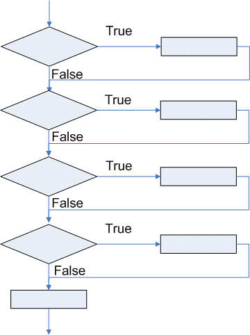
The attribute option compulsorily evaluates the conditions for all the options provided in the definition code. All the definitions satisfying the evaluation conditions are applied to the resultant definition. This means that it is not always easy to write the code where just want one of the options to be applied, the programmer have to make sure that other options are not applied using a negative condition.
The attribute Switch supports these types of scenarios where evaluation is to be carried out only up to the point where the first evaluation condition is satisfied.
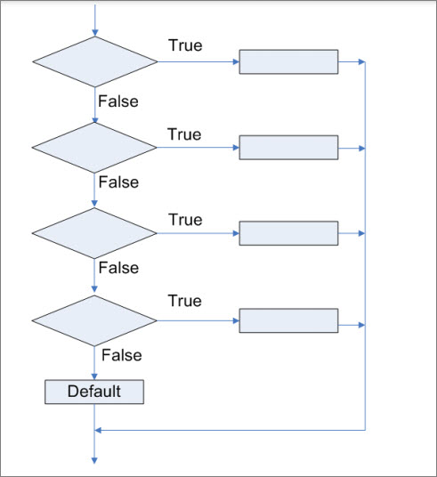
Modifier (Switch-Case)
Switch is an attribute which is similar to the Option attribute but reduces code complexity and improves the performance. Once a condition is satisfied from one group, switch will not check further conditions from the same group. It evaluates the conditions from the other groups specified, if any.
The Switch are grouped using a label. Therefore, multiple switch groups can be created and zero or one of the switch cases would be applied from each such group.
Apart from this, the switch can be grouped using a label, as shown below:
Syntax
Switch : Label : <Definition Name> : <Condition>
Switch : Label : <Definition Name> : <Condition>
Where,
< Label > is any string combination used to group
< Definition Name > of same definition type in which the switch modifier is used.
< Condition > when true the optional definition will be used.
Example:
[Field: Sample Switch]
Set As : “Default Value”
Switch : Case1: Sample Switch1: ##SampleSwitch1
Switch : Case1: Sample Switch2: ##SampleSwitch2
Switch : Case2: Sample Switch3: ##SampleSwitch3
Switch : Case2: Sample Switch4: ##SampleSwitch4
[!Field: Sample Switch 1]
Set As : “Value from Sample Switch 1”
[!Field: Sample Switch 2]
Set As : “Value from Sample Switch 2”
[!Field: Sample Switch 3]
Color : Released Blue
[!Field: Sample Switch 4]
Color : Released Orange
Let us say that the value of the two variables Sample Switch1 and Sample Switch3 are true. In this case the field Sample Switch will display text Value from Sample Switch 1 in Released Blue color.
Sequence of Attribute and Modifier Evaluation
The final set of attributes applicable to the definition are evaluated based on the internal order of evaluation of attributes and modifiers. The order of evaluation of the attributes and modifiers is as specified as below:
- Use
The Use attribute is evaluated first irrespective of the order where it is specified in the definition description.
- Definition Specific Attributes
Attribute that are not pre-fixed with an attribute modifier. The attributes are evaluated in the order of specification.
- Add/Delete/Replace
Add/Delete/Replace are referred to as delayed attributes because even if they are specified within the definition in the beginning their evaluation will be delayed till the end within static modifier and Definition specific attributes.
- Option
The option conditions are evaluated on runtime based on the user selection.
5. Switch
The switch conditions are then evaluated on runtime based on the user selection.
6. Local
The local modifier is evaluated in the end, on runtime based on the user selection.